


3-Line EMI Filter, Series A
Construction
3-phase, 3-wire filter
Metal case
Various terminal connection configurations
Features
1. High insertion loss
2. Excellent EMI noise suppression
3. Optimized for long motor cable and operation under full load
4. Guaranteed compliance with EN 55011/IEC 61800-3
5. Design complies with IEC 60939, UL 1283, CSA 22.2 No.8
Inverters and Frequency Converters Applications
Elevators, cranes, traction system
HVAC systems (heating, ventilation and air conditioning)
General three phase motor drive systems
Machine tools: printing machine, packaging machine, milling and drilling machine,
Textile machine
Three-phase power supplies and UPS
Technical Data
| Rated voltage(VR) | 440VAC, 50/60Hz |
| Rated current(IR) | 5 ~ 1200A @ 40 °C |
| Test voltage(VP) | 2250VDC, 5S(Line to line) 2550VDC, 5S(Line to case) |
| Temperature range (operation and storage) | -25 °C /+85 °C (25/085/21 IEC 60068 − 1) |
| Overload capability (thermal) | 1.5 x IR 3min/hour 2.5 x IR 30s/hour |
Filter Selection Table
| Filter type | Rated current @40°C [A] | Typical drive power rating[KW] | Leakage current @400VAC/50Hz [mA] | Rtyp[mΩ] | Input/Output connections | Dimensions | Weight | ||
| NFI-0005-SA | 5 | 0.75 ~ 1.5 | < 6 | 18 | √ | Picture A | 0.8 | ||
| NFI-0010-SA | 10 | 2.2 ~ 4 | < 6 | 7 | √ | Picture B | 1.5 | ||
| NFI-0020-SA | 20 | 5.5 ~ 7.5 | < 6 | 7.4 | √ | Picture C | 2.8 | ||
| NFI-0036-SA | 36 | 11 ~ 15 | < 6 | 3.7 | √ | Picture C | 3 | ||
| NFI-0050-SA | 50 | 18.5 ~ 22 | < 6 | 2.1 | √ | Picture C | 3.1 | ||
| NFI-0065-SA | 65 | 30 | < 10 | 1.9 | √ | Picture D | 5 | ||
| NFI-0080-SA | 80 | 37 | < 10 | 2.3 | √ | Picture E | 7.2 | ||
| NFI-0100-SA | 100 | 45 | < 10 | 2.1 | √ | Picture E | 7 | ||
| NFI-0150-SA | 150 | 55 ~ 75 | < 10 | 1.9 | √ | Picture E | 7.7 | ||
| NFI-0200-SA | 200 | 90 | < 30 | 0.4 | √ | Picture F | 5.5 | ||
| NFI-0250-BA | 250 | 110 ~ 132 | < 30 | 0.22 | √ | Picture G | 6.9 | ||
| NFI-0300-BA | 300 | 160 | < 30 | 0.21 | √ | Picture G | 6.9 | ||
| NFI-0400-BA | 400 | 200 | < 30 | 0.1 | √ | Picture H | 12 | ||
| NFI-0600-BA | 600 | 215 ~ 315 | < 30 | 0.13 | √ | Picture H | 12.4 | ||
| NFI-0900-BA | 900 | 400 | < 30 | 0.19 | √ | Picture I | 21.5 | ||
| NFI-1200-BA | 1200 | 630 | < 30 | 0.12 | √ | Picture I | 21.7 | ||
Note: If the leakage current of the filter is greater than 0.5mA, the product should not be used unless there is reliable grounding connection and protective measures. Otherwise, the risk of electric shock exists.
Electrical Diagram
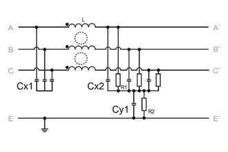 NFI-0005-SA~NFI-0036-SA
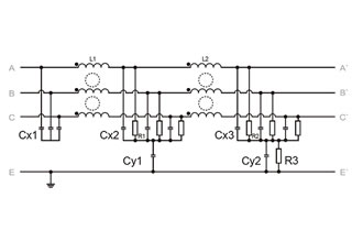 NFI-0050-SA~NFI-1200-BA
Conducted emission measurement
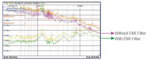
| Hz (MHz) | 0.15 | 0.5 | 1 | 5 | 10 | 30 |
| Input side noise level without EMI Filters(AV/dBμV) | 92 | 84 | 80 | 66 | 61 | 44 |
| Input side noise level with EMI Filters(AV/dBμV) | 20 | 25 | 34 | 32 | 40 | 36 |
| Noise damping factor due to EMI Filter application | 3981-fold | 891-fold | 199-fold | 50-fold | 11-fold | 2.5-fold |
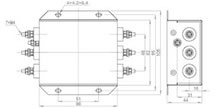
Product Size
 Picture A
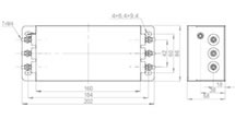 Picture B
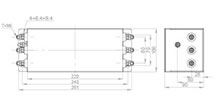 Picture C
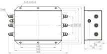 Picture D
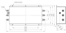 Picture E
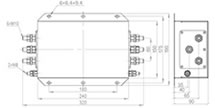 Picture F
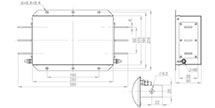 Picture G
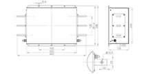 Picture H
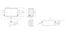 Picture I
Insertion Loss (typical values at Z=50Ω))
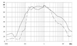 NFI-0005-SA
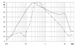 NFI-0010-SA
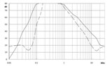 NFI-0020-SA
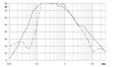 NFI-0036-SA
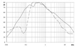 NFI-0050-SA
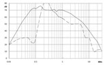 NFI-0065-SA
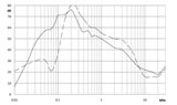 NFI-0080-SA
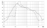 NFI-0100-SA
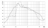 NFI-0150-BA
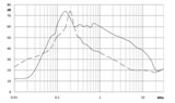 NFI-0200-BA
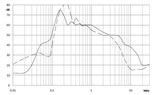 NFI-0250-BA
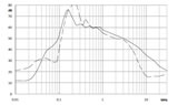 NFI-0300-BA
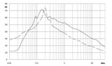 NFI-0400-BA
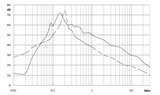 NFI-0600-BA
 NFI-0900-BA
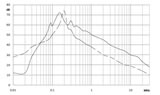 NFI-1200-BA
common mode
differential mode
| User name | Member Level | Quantity | Specification | Purchase Date |
|---|


